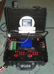
I've been working on building a portable test bench for some time now. It helps when going over to friends houses to test games and to work on the PCB's outside of the cabinet.
One of the challenges is finding a display that is small enough to fit inside the case.
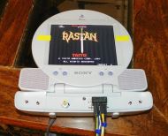
I started out with a regular Head Rest LCD TV that people use in vehicles. The picture on that was horrible, and you had to convert RGB to Composite to use it, so I needed to find something better. After doing a lot of research, it turns out a lot of people were using the portable LCD screen for the Playstation 1 (PSOne LCD).
Most of the information on the net talks about soldering directly to the LCD PCB, or decasing the monitor and tieing into the harness that's already there.
I decided to take a different approach. I like to think it's a better approach, but that might be a biased opinion :)
My approach is to remove the pass-through connector from the back of the LCD and use that to build an adapter.
The main advantage is, that if the LCD dies for some reason, I can simply replace the LCD with another one, and I won't have to mod it. It's about the same amount of work (a little extra removing the extra connector), but the results look a little cleaner. As a bonus, if you're not using it to repair Arcade Games, you can still use it on the PSOne with out having extra wires or connectors on it.
I started with this PDF:
Which gives you the basic pin out of the connector. After a little more research, I determined that pins 4 and 2 are for Audio and that pins 3 and 1 are for audio ground.
The only other pins that you need to worry about are pins 5, 8, 9, 11, and 12. In the pictures you will see that I wired up pin 10, but for my LCD screen it wasn't necessary. In the end I wound up cutting that wire off.
So step 1 is to remove the pass through connector. This is the most painful part since you have to open the lower half of the LCD to get the board out. If you were soldering wires directly to the PCB, you would still need to do this step.
To get into the case, you need to remove the three screws and then pry the plastic up with a flat head screwdriver. It's going to take some patience, so don't force it too much.
Once you have the case open, you'll then need to desolder the pass through connector. After you have removed that, you can put it all back together and we can work on building the adapter.
If you look at the PDF above, you'll see that the pins are staggered up and down. If you're looking at the back of the connector with the pins facing down, pin 12 is on the top left side. Pin 11 is on the bottom left side.
So now you need to solder a wire to each of the following pins:
12 = Green Video
11 = Red Video
9 = Blue Video
8 = Video Ground
5 = Composite Sync
4 = Left Audio
3 = Left Audio Ground
2 = Right Audio
1 = Right Audio Ground
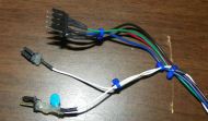
I then put heat shrink on each of the wires to keep anything from shorting and to make it look nicer.
On the other end of the wires I used two Molex .156 KK headers for the Video and one 4 pin .093 Molex connector for the Audio. The Audio input accepts Line Level inputs, so if the arcade game has amplified audio, you'll want to convert that to line level. There are adapters out there that do that for you, you'll just need to search for it.
The reason I used two .156 KK headers. for the video is due to a Sync issue I ran into with some JAMMA PCB's (Double Dragon and CHELNOV: Atomic Runner). For some reason they wouldn't sync vertically to the monitor (picture would constantly roll).
After a lot of playing around, I ran into something very strange. If I held each sync wire in each hand, the picture was rock solid. If they were just connected and I powered it up, it wouldn't sync. The weirder part was if I held each wire the picture was rock solid, then if I connected them after holding them separate, and let go, the picture would stay rock solid!
So after doing more research, someone suggested putting a cap inline with the sync wire. So I dug out a cap that was close to what they recommended and put it inline and it worked!
The cap is a ceramic/mylar cap 1KV 561, which is around 5,600pF (.0056uF). Apparently that is enough to get the picture to sync up.
UPDATE 2/10/2013
Apparently some games won't Sync WITH the cap in place, so I re-did the connectors. It now has two connectors, one with the Cap and one without the Cap in order to accommodate PCB's that have different syncs.
I also switched from the 9 Pin Molex connector to the KK style connectors. This allows me to use the monitor to test games in the cabinets.
Videos
Here are a couple videos on the process. The first one is one I made on (2/10/2013) that shows how to build the adapter from start to finish. The second video is from a KLOV member doing their mod.
Broodwich from the KLOV forums has put up a YouTube video showing the mod that he did.