Intro
Date 4/4/2008
 If you haven't picked up the April 2008 copy of Game Room Magazine, you should head over there now and pick up a copy! It goes into more detail about how this project came about and has some really great pictures from Dan Coogan. If you haven't picked up the April 2008 copy of Game Room Magazine, you should head over there now and pick up a copy! It goes into more detail about how this project came about and has some really great pictures from Dan Coogan. I decided to build a MP3 Jukebox after looking around for a real one. After getting sticker shock for most of the Jukes that I was interested in, I decided this would be the better route. I shared the idea with my brother Mike and he liked the idea and offered to help me. Without his help, the end result wouldn't have been nearly as nice! This page describes the process of designing and building RoboJuke 2084!
|
Are you mocking me?
Date 4/4/2008
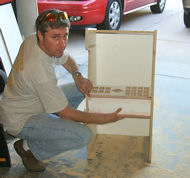
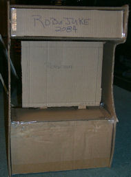 The first step in the design process was to make a carboard prototype. Nothing fancy, just something so I could get a general idea of what it should look like and how things will be placed. The first step in the design process was to make a carboard prototype. Nothing fancy, just something so I could get a general idea of what it should look like and how things will be placed. Thanks go out to Dave Giarruso for the help with the design of the sides. Dave took a picture of a Robotron and created a 1/2 scale template for me. I took the template and printed it on my wide format printer (does 19x23) in two pages and taped the results together.
|
Made a template
Date 4/4/2008
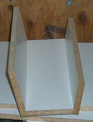
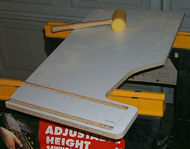 After doing the cardboard mockup, we decided to create a template in case we wanted to build more then one. By having the template, it would make setting up the tools a lot easier. After doing the cardboard mockup, we decided to create a template in case we wanted to build more then one. By having the template, it would make setting up the tools a lot easier. We built the template out of 5/8" Melamene since it's what I had lying around. After working with Melamene, I've come to the conclusion that unless you want the Melamene sides (i.e. you're not going to paint it), use Plywood or MDF. The reason is due to the fact that painting Melamene sucks big time.
|
Mocking up the template
Date 4/4/2008
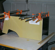
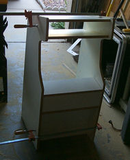 We cut the sides out with a Jig Saw and cut all the other pieces out on my table saw. For the Dado and Rabbet cuts we used a router with a 5/8" bit. We cut the sides out with a Jig Saw and cut all the other pieces out on my table saw. For the Dado and Rabbet cuts we used a router with a 5/8" bit. After cutting everything out, we did a test assembly to make sure everything was going to fit together correctly and make any adjustments as necessary. The main adjustments we had to make were to cut the two top pices at an angle so they would sit flush with the back of the cabinet.
|
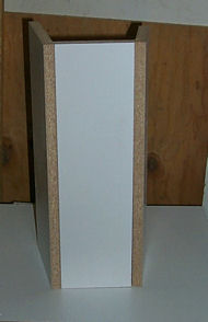
Eveything fits!
Date 4/4/2008
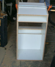 As you can see, everything went together pretty nice. Again, this is only the template, and not the actual Juke yet. As you can see, everything went together pretty nice. Again, this is only the template, and not the actual Juke yet. After we made sure everything was just right, we cut out the parts for the real juke. Having the template made it a snap. The template took us several days to make as we did a lot of the designing on the fly and had to correct a few mistakes. Building the second one using the templates took us only a few hours.
|
Control Panel
Date 4/4/2008
 When building the control panel, we looked at the real thing (Joust in this case) and measured all the angles, and looked at how it was constructed. Then we built a half scale version of it. When building the control panel, we looked at the real thing (Joust in this case) and measured all the angles, and looked at how it was constructed. Then we built a half scale version of it. Making this without a table saw would have been a lot tougher!
|
More Control Panel
Date 4/4/2008
 As you can see, everything is still square. To round off the edges like the real control panel, we used a hand sander. The one advantage to particle board is that it shapes pretty easy. If we had used Plywood, I probably would have used a router first, then sanded. As you can see, everything is still square. To round off the edges like the real control panel, we used a hand sander. The one advantage to particle board is that it shapes pretty easy. If we had used Plywood, I probably would have used a router first, then sanded. Since the pieces fit together pretty well, we didn't need to clamp it when we glued it together. Simply applied glue, lightly tapped the pieces with a rubber mallet to make sure the pieces were snug and let it dry.
|
Button Layout
Date 4/4/2008
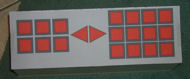 For the button layout, I measured out the buttons and created a template in PaintShop Pro. After I printed out the template, used an Exacto knife to cut out the red squares and triangles. For the button layout, I measured out the buttons and created a template in PaintShop Pro. After I printed out the template, used an Exacto knife to cut out the red squares and triangles. If I had to design the control panel again, I would make it about 1/4" wider and a 1/4" deeper on the top. The way it is now, everything is VERY cramped. It also made wiring a lot more tedious.
|
Holes drawn
Date 4/4/2008
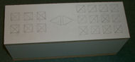 Once the control panel layout template was printed and cut out, I used it to mark the control panel for drilling and routing. Once the control panel layout template was printed and cut out, I used it to mark the control panel for drilling and routing.
I made an X through the boxes to make it easier to find the centers when drilling.
|
That's a lot of work!
Date 4/4/2008
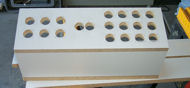 Since I don't currently own a drill press (it's on my shopping list!), I hand drilled all 20 holes. This was a major pain and if I ever make another one, I'm making a run to Home Depot to pick up a drill press! Since I don't currently own a drill press (it's on my shopping list!), I hand drilled all 20 holes. This was a major pain and if I ever make another one, I'm making a run to Home Depot to pick up a drill press! After drilling the 20 holes we then had to hand route out all the holes (about 1/8" deep) square (and two triangles) so the buttons would sit flush on the panel. Not a fun thing to do free-hand, but the results were great.
|
Look! Buttons!
Date 4/4/2008
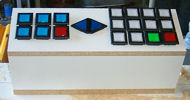 Here we mocked up the control panel after drilling the holes. Here we mocked up the control panel after drilling the holes.
This was done prior to routing out the holes so you can see how the buttons are not flush with the top.
|
Mike showing off the Control Panel
Date 4/4/2008
 Here is my brother Mike showing off the control panel that has been freshly drilled and sanded (rounding the two edges). Things are starting to come together now! He deserves the credit for hand routing the holes! Here is my brother Mike showing off the control panel that has been freshly drilled and sanded (rounding the two edges). Things are starting to come together now! He deserves the credit for hand routing the holes! We also used some bondo to fill in the minor cracks at the edges of the control panel to make sure it was perfectly smooth before painting.
|
It's Painting time!
Date 4/4/2008
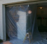 In order to paint the parts, we setup a make-shift paint booth in my garage. Basically a tarp on the ground and plastic hung from the garage door when it was open. To attach the plastic we found small aligator clips at Home Depot that made putting up and taking down of the paint booth a breeze. In order to paint the parts, we setup a make-shift paint booth in my garage. Basically a tarp on the ground and plastic hung from the garage door when it was open. To attach the plastic we found small aligator clips at Home Depot that made putting up and taking down of the paint booth a breeze. It worked out pretty well, but it's not without it's problems. You work with what you have :-) We used an air compressor and paint gun to paint the cabinet. If you have an option to use a paint gun, do it. The results are night and day from anything else.
|
Parts get a coat!
Date 4/4/2008
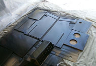 All the parts get a nice coat of Glossy Black, except for one side of each side piece which will be painted Robotron Silver. A big thanks to Brian Jones for providing the paint codes! All the parts get a nice coat of Glossy Black, except for one side of each side piece which will be painted Robotron Silver. A big thanks to Brian Jones for providing the paint codes! This is actually the SECOND time we painted the parts. The first time we found out that the paint doesn't stick to melamine worth a damn! When we painted it the first time and started sanding it for a second coat, the paint and primer were coming off. We had to sand everything down and we sanded the melamine off the sides down to the particle board. After that we primered and repainted. A much better result the second time. We let that dry, then sanded and hit it with one final coat of black.
|
Paint the Fence! Uuuuuup.... Dooooownn.
Date 4/4/2008
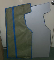 Using Painters tape and Paper we covered the side that was painted black. Once the black sides where covered up we hit the other sides with primer and two different colors. A base coat and then a top coat, the same as a real Robotron. Using Painters tape and Paper we covered the side that was painted black. Once the black sides where covered up we hit the other sides with primer and two different colors. A base coat and then a top coat, the same as a real Robotron. Once that was dry we sanded again (600 grit each time), and hit all the parts with a clear coat of polyeurothane. The problem with the clear coat we used, is it caused the silver sides to yellow a bit. It worked great for the black, but horrible for the light. Oddly enough, under the artificial light, the sides look correct. Take it out in natural light and they have a gold tint to them. Wierd... lucky for me, it's staying inside :-)
|
Some Assembly required...
Date 4/4/2008
 This is one step we should have done BEFORE painting. Once everything was painted it made the assembly a lot harder because now the pieces fit even snugger then before due to the exta thickness added by the paint. This is one step we should have done BEFORE painting. Once everything was painted it made the assembly a lot harder because now the pieces fit even snugger then before due to the exta thickness added by the paint. Oh well, live and learn. The results still turned out ok. If I was to build another one, I would use BLACK melamine and just sand down the outsides. This would also save on painting and time. We assembled and glued in two steps. The first step was to glue all the inner pieces in place, then the second part was the back pieces. Before the back pieces were glued in, we installed the two Fans at the top. With the back piece glued in, it would have required a lot more effort. If the fans do fail at some point, they will have to be replaced from the front, and that won't be fun :-(. The amount of use that it will get though, the fans should last for many years.
|
Back to the Control Panel
Date 4/4/2008
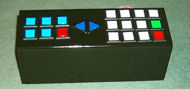 Now that everything is painted again, it's time to put all the buttons in and get everything wired up. It wasn't important to make sure the buttons were lined up at this point since I needed to open the buttons up and put labels in there anyway. Now that everything is painted again, it's time to put all the buttons in and get everything wired up. It wasn't important to make sure the buttons were lined up at this point since I needed to open the buttons up and put labels in there anyway. The control panel turned out to be the coolest part of the project.
|
Wires, lots of wires!
Date 4/4/2008
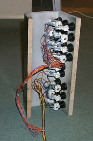 This was the most tedious part of the entire project. I had to wire up each of the 20 buttons. That's a total of 80 wires. Two wires for the switch function, and two wires for the bulbs. This was the most tedious part of the entire project. I had to wire up each of the 20 buttons. That's a total of 80 wires. Two wires for the switch function, and two wires for the bulbs. The bulbs are rated at +14V DC and I tried running them at +12V DC but they made the buttons way too warm to the touch for my liking. So I wired them as +5V DC. They are not as bright, but that actually worked in my favor since it doesn't distract from the rest of the juke.
|
The Guts!
Date 4/4/2008
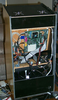 After wiring up the control panel, it was time to put everything else inside. We built an L shaped shelf for the 15" LCD monitor to sit on. On the back side of that shelf, we mounted the Motherboard, and I-PAC controller. After wiring up the control panel, it was time to put everything else inside. We built an L shaped shelf for the 15" LCD monitor to sit on. On the back side of that shelf, we mounted the Motherboard, and I-PAC controller. We then added another shelf that we used to mount the Power Supply (450W), Hard Drive (40GB) and a Power Strip. The Amp (100W Car Amp) was mounted in the bottom of the cabinet.
|
Conclusion
Date 4/4/2008
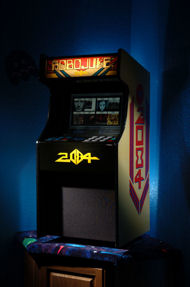 It was a lot of fun, but it was a lot of work. We probably won't build another one for a long time. If we do, I'll probably get the parts run through a C&C Machine. It was a lot of fun, but it was a lot of work. We probably won't build another one for a long time. If we do, I'll probably get the parts run through a C&C Machine. I would like to thank Brian Jones for the outstanding art work that is on the cabinet! He created stickers for the 2084 side art and the 2084 that is on the front of the control panel. He also created the Marquee image for me which I had printed at MameMarquees.com A lot of other details went into the design and building of the Juke: The marquee lights up via a florescent light. The Marquee is held in place by two brackets like a real game has. The Back door has a lock on it and was built like most arcade back doors are. The control panel is on a hinge and latches like the real thing. The speakers are hidden by a speaker grill that we built. There is a cardboard bezel infront of the monitor to hide the shelfs and block any light from showing from the inside. The monitor is protected by a clear bezel and is secured with a bracket like other arcade games. The fans have nice shiny metal covers which really pop against the black. The cabinet has Leg Levelers on it. The cabinet has T-Modling. The stand it sits on uses the black light carpeting. If you are thinking of building your own, just remember it is a LOT of work, but it is a very rewarding experience!
|