Date 3/27/2000
 For some reason, a lot of OPs decide that they no longer need the ground pin on the power cord and snip it off. Games are grounded for a reason. Safety. Most of the time, you wont see a problem with having the ground pin missing, but that one time can be a shock! (Pun Intended). For some reason, a lot of OPs decide that they no longer need the ground pin on the power cord and snip it off. Games are grounded for a reason. Safety. Most of the time, you wont see a problem with having the ground pin missing, but that one time can be a shock! (Pun Intended). I started by replacing the power cord on my Defender. This was a scary proposition since the game works perfectly :-) I wanted to have a lot more pictures for this tutorial, but they didn't turn out very well and since I took them as I went, there wasn't a chance to go back and take them again. So lets get started:
Tools you will need: Soldering Iron (Flat Tip is best) Phillips Screw Driver Pliers Dykes Volt Meter or Continuity tester Desoldering Tool Supplies you will need: New power cord Solder Estimated Time to complete:
30 - 60 Minutes
|
Step 1
Date 3/27/2000
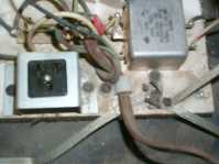
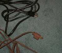
 Open the back of the game, make sure it is unplugged. Then you will need to locate where the current power cord is attached like in the picture above.Make a diagram of where all the wires are attached. Pay attention to the current power cord, it might make it easier to identify which side is connected where. Open the back of the game, make sure it is unplugged. Then you will need to locate where the current power cord is attached like in the picture above.Make a diagram of where all the wires are attached. Pay attention to the current power cord, it might make it easier to identify which side is connected where. The power cord I had on my Defender had a smooth side and rough side (ridges). This told me that the rough side went to the left Prong (if it was plugged into the wall) and the smooth side that went to the right plug. I then used a Volt meter (Continuity setting) to see which side the Black and White wires went to on my new cord. I marked all this on my Diagram.
|
Step 2
Date 3/27/2000
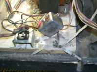 In the case of this game, you will want to unscrew the metal block from the power supply board and the plastic clip that is holding the power cord on the power supply board. In the case of this game, you will want to unscrew the metal block from the power supply board and the plastic clip that is holding the power cord on the power supply board.
This will make it easier to desolder the wires from the metal block.
|
Step 3
Date 3/27/2000
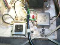
Desolder the three wires. I started with the one that is attached to the Fuse block since it was the easiest one to get to. I then did the Ground [Green] wire in the middle of the metal block since it was the only wire attached to that terminal. I then removed the last wire from the top terminal. It took the most time since it was attached with another wire and a capacitor. Take your time when doing this and don't rush. Remember that heat kills and the hotter the metal block gets, the higher the risk of doing damage. If its being stubborn, stop for a sec, take a deep breath, and try again. I use the Desoldering tool to remove the excess solder while I'm trying to remove the wires. The pliers come in handy when you want to pull the wire out while heating the solder without burning your fingers :-) In the case of the middle wire (the ground wire), I found it easier to clip it with the Dykes and to desolder it that way.
|
Step 4
Date 3/27/2000
Once everything is desoldered you might want to clean it up a bit and make sure you can see the holes in the middle of the metal tabs that you are going to be soldering to. You don't need to worry about this for the fuse holder, but for the metal box its important.
|
Step 5
Date 3/27/2000
It helps if you "tin" the ends of the wires on the new power cord, this makes all the strands stick together (easier to put through the hole) and when you get ready to solder the wire it allows you to "Stick it in place" and gives you a free hand to hold the spool of solder.
|
Step 6
Date 3/27/2000
I started with the wire on the top of the metal box since it would be the most awkward to deal with when soldering wires back on and I didn't want a bunch of other wires getting in the way. Feed the wire through the hole (I had to snip some of the wire off since it was too big with the solder on it) and bend it over. Heat the wire so the solder melts enough to "Stick" to the tab. After that apply more solder and heat enough so it all melts together.
|
Step 7
Date 3/27/2000
Now do the ground wire in the middle, same techniques and rules applies as before.
|
Step 8
Date 3/27/2000
Now do the wire to the Fuse holder. This one you just heat up so it sticks to the tab (and other wire) then add more solder so it is connected solidly.
|
Step 9
Date 3/27/2000
Now its time to screw everything back down. Once you do that, you're done and its time to hit the final step.
|
Step 10
Date 3/27/2000
 Ok, its time to double check EVERYTHING. Ok, its time to double check EVERYTHING.
Make sure you soldered the right wires to the right places, make sure you don't have any extra solder lying around, not strands of wire lying around. Make sure the wires are soldered on nice and tight. Give them a little tug. If they come off, you know you didn't do it right. SMOKE TEST
|
SMOKE TEST!
Date 3/27/2000
Yep, its time to see if you did it right. Plug it in, turn it on. If you see SMOKE, you didn't do it right. TURN IT OFF! (If you see Smoke, Sparks, Read Glowing Embers, or the power supply starts to melt down). If any of those happen, then you need to go back and double check EVERYTHING again. Check for shorts (i.e. two wires touching that shouldn't), make sure all the wires are attached to something and that something is the right something. This is actually probably one of the easiest things you will be doing, so I doubt that you'll do it wrong, but you never know. If you are really paranoid, you can unplug everything and use a voltmeter to test the voltages. If you are only half brave, maybe you'll just unplug the boards and leave the monitor plugged in to test with. Personally, if I'm going to screw something up, I'm going to do it right! :-)
|
Date 3/27/2000
 Well, that's all there is to it. Well, that's all there is to it.
As you can see, the new cord even looks better. If you have any questions, comments or need clarification, please feel free to drop me an Email and I'll see what I can do.
|