Date 3/27/2000
I don't think I've ever seen a Nintendo game yet that didn't use the Sanyo 20EZ monitor. If you have a Nintendo that is original, chances are you have one. As time passes the Capacitors in the monitor deteriorate and eventually fail. You'll get numerous symptoms from a scrambled screen to no picture at all. What fixes most of these problems is a simple "Cap Kit". Colors may bleed, the image may look blurry (Did you try cleaning the screen first? You'd be amazed at how dirty they get), or as in my case, it kept shutting itself down when powered up. I would like to thank Al Warner for his excellent article on doing Cap Kits. Please read his article before continuing on here.
|
Disclaimer:
Date 3/27/2000
This information is provided to you "AS-IS", if you proceed with the process of doing a "Cap Kit" you do so at your own risk. If you are unsure of what you are doing, or have reservations about doing one, do not do this. It is recommended that you ask someone locally who has done one to walk you though it. However, if you are brave enough and are willing to take the risk, then keep reading. Also be warned that this information may contain errors. I have done my best to ensure that this information is correct to the best of my ability. If you do find an error or inaccuracy, please let me know and I will try to fix it when I can. This information is meant to a GUIDE and is not to be used literally. Every situation is different and you need to use your better judgement when you do your "Cap Kit" If you want to know what 19,000 Volts can do to a monitor, you may want to take a look at this article in the Repair Log
|
Date 3/27/2000
A word of caution before you proceed. Working on monitors can be very dangerous and if you ignore the warnings given here and other places, it could cost you your life. A Monitor stores a charge even after it has been off for an extended period of time. This charge is in the 19,000+ Volt range.
|
The Tools Needed
Date 3/27/2000
The tools I used are: - Discharging Tool
- Cap Kit
- Needle Nose Pliers
- Snips
- 2 different sized Phillips screw drivers (the short one is a MUST for getting the screw under the PCB on the right side of the monitor)
- Double ended screwdriver is only needed if you drop a screw in a place you cant reach with your fingers.
- Soldering Iron
- Desoldering Tool
The tools listed above should do the job nicely on a Sanyo and most other brands, however, like I said, every situation is different and if you have a better tool for the job, use it.
|
Before You Start!
Date 3/27/2000
Make sure that the game is turned OFF and UNPLUGGED. You can not discharge a monitor that is on and it could be extremely hazardous if you try! Once you have made sure the game was turned OFF and UNPLUGGED, what you need to do is to Discharge the monitor. This is the most dangerous part. If you do not have a discharging tool, I suggest you make one, or buy one from Bob Roberts. The one in the Picture is from Bob Roberts. Remember that the tube still holds 20,000+ Volts so be careful when you do this. Monitors can also get extremely dirty, so you shouldn't wear anything that you don't want ruined. I washed and dried my hands about 5 times during the procedure because they got so dirty that I was leaving smears on everything I touched.
|
Discharging the Monitor
Date 3/27/2000
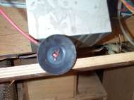
 Discharging is easy, but scary. I particularly like Bob Roberts Discharging tool since it keeps me further away. Every little bit helps :-). Discharging is easy, but scary. I particularly like Bob Roberts Discharging tool since it keeps me further away. Every little bit helps :-). Start by clipping the wire to the metal chassy of the monitor. Make sure its on secure. Next, put one hand in your pocket (this is for safety). After that hold the wooden part of the discharging tool and slide the blade of it underneath the rubber suction cup of the 2nd Anode until you touch the metal clip. Don't Worry if the metal part of the Discharging tool is touching the chassy, just make sure you are NOT touching it.
|
Date 3/27/2000
 When you slide the blade under the suction cup, you may hear a loud "CRACK!", or you might not hear anything at all. I always leave it under there for a few seconds "Just in Case". Call it Paranoia if you want, but I'm not willing to take a chance :-) If you still don't feel really comfortable, discharge it a second time. I usually do, "Just in Case" :-) When you slide the blade under the suction cup, you may hear a loud "CRACK!", or you might not hear anything at all. I always leave it under there for a few seconds "Just in Case". Call it Paranoia if you want, but I'm not willing to take a chance :-) If you still don't feel really comfortable, discharge it a second time. I usually do, "Just in Case" :-) At this point the monitor should be discharged. NOTE: The tube may still contain a small charge so you should still treat it with respect or it might bite you. Once its discharged you can remove the suction cup by squeezing it together and sliding it out one side, then the other. This will take some practice and patience if you have never done this before. You can lift up the edge of the suction cup to see what you are doing as well. Just don't touch the metal clip. Do not stick anything in the hole either. Even with the wire disconnected, you run the risk of getting shocked.
|
Step 1
Date 3/27/2000
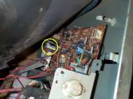
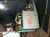 After the monitor has been discharged and the second anode wire has been disconnected, its time to start disassembling the monitor to the point where we can work on it. After the monitor has been discharged and the second anode wire has been disconnected, its time to start disassembling the monitor to the point where we can work on it. We will start with the Fly Back Cage. The first thing we remove are the three Molex connectors circled in the picture. The board on top of the Fly Back Cage is the Video Inversion Board for the Nintendo Games.
|
Step 2
Date 3/27/2000
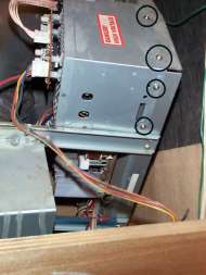 Next remove the 4 screws holding the cage in place. Next remove the 4 screws holding the cage in place.
Once you remove those screws the cage will slide to the left. You will have to slide the wires out of the clips that hold them in place on the back side of the cage. This can be a real pain in the ass, but its the only way you will remove the cover. NOTE: In this picture, the wires have not been removed yet. You can do it in either order, just make sure you do both :-)
|
Step 3
Date 3/27/2000
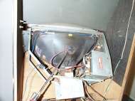
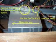 Next we move to the Neck Guard. This guard is here to protect the Neck of the Tube, be very careful when you are doing the "Cap Kit" that you do not hit the Neck with anything. If you crack the tube, its toast and it could cause you serious injury. Next we move to the Neck Guard. This guard is here to protect the Neck of the Tube, be very careful when you are doing the "Cap Kit" that you do not hit the Neck with anything. If you crack the tube, its toast and it could cause you serious injury. There is a screw at the top and the bottom of the neck guard (might even be a total of 4, but this one only had 2). You might also have wires tied to it like mine in the picture. Once you remove the screws and cut the tie, you slide it to the left and carefully remove it. If its dirty, you can clean it and put it aside.
|
Step 4
Date 3/27/2000
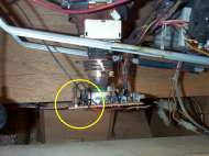 Now that you have the Neck Guard off, you will see the neck board and a ground wire that is attached via a quick disconnect. Now that you have the Neck Guard off, you will see the neck board and a ground wire that is attached via a quick disconnect.
Carefully remove the wire and unwrap it from the Neck Board. After you have removed that, its time to take the Neck Board off the Neck. WARNING! This board is fragile and can be cracked VERY easily. DO NOT FORCE IT. Use both hands and gently rock it back and forth and pull on it gently until it slides completely off. If you break the board, its going to ruin your whole day, so be gentle with it.
|
Step 5
Date 3/27/2000
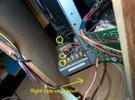 Now we want to start removing the three small boards next to the main PCB that we will be working on. Now we want to start removing the three small boards next to the main PCB that we will be working on.
These boards are for the monitor adjustments and a few other things (which I'm not sure what they are). Each one is held in by a single screw. These may be hard to get at like in my Popeye pictured here due to the cramped space. The other ends of the boards are held in place by metal tabs. Once you take the screws out, just let these hang freely for now. Make sure they don't hit the neck of the Tube.
|
Step 6
Date 3/27/2000
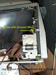 Now we start to remove the PCB by undoing the two screws holding it in place. Now we start to remove the PCB by undoing the two screws holding it in place.
You will need the short Phillips to remove the bottom screw since you have to get to it from the bottom side of the monitor (faces the cabinet wall). You will also find several Plastic Clips such as those found on a PC that is holding the PCB in place. Use the needle nose pliers to squeeze them and push them through the holes. You might find it easier to do it from the Top rather than the bottom.
|
Date 3/27/2000
 If you look at the bottom of the monitor you will also see several Black clips. If you look at the bottom of the monitor you will also see several Black clips.
Squeeze them from the bottom of the monitor and push them up. These are the clips that hold the wires in place. This will be A LOT easier than trying to remove the wires from the clips. After that, there are a few more white clips that you will want to remove the same way, you'll figure out which ones they are :-)
|
Date 3/27/2000
After doing this, the PCB should be loose enough that you can pull it towards you. NOTE: You will not be able to completely remove the PCB from the monitor because a few wires are still attached. This is not a problem since we can do the cap kit easily enough with it still attached. You want to disconnect the ground wire in the second picture. This will make moving the PCB around a lot easier.
|
Step 7
Date 3/27/2000
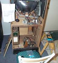 Pull the PCB out carefully to where you can work on it. Pull the PCB out carefully to where you can work on it.
Get out your list of Cap locations and have it handy. Plug in the soldering Iron and have a seat. You'll be here awhile. This is where it starts to get fun. Its a big game of hide-n-go-seek. Your job is to find where they have hidden all the caps on your list and to replace them. Most of the locations are printed on the bottom of the PCB, however, one of the caps (C458 if I remember correctly) is not labeled on the bottom and you have to look for it from the TOP.
|
Step 8
Date 3/27/2000
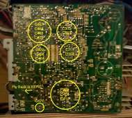
Start Replacing Caps. The picture on the right gives you and idea of where you can find the caps that you need to replace. NOTE: When you replace the Cap make sure that you get the polarity correct. If you don't the Cap will explode when you power the monitor on! (So I've heard) If that happens then you'll have to go through this ALL OVER AGAIN. Double check the Cap you are removing against the one you are putting in its place. They should be the same or very close. A few in the Kit from Bob are different from the ones I removed but I trust Bob and he's been doing this for a LONG time. The kits from Zanen may also contain slightly different caps then what you are removing.
|
Date 3/27/2000
 A word of Caution. When soldering be VERY careful not to get excess solder on the PCB. Be careful that you do not solder things together that were not meant to be soldered together. Space is at a premium on this PCB and you could easily join things that are not supposed to be joined. A word of Caution. When soldering be VERY careful not to get excess solder on the PCB. Be careful that you do not solder things together that were not meant to be soldered together. Space is at a premium on this PCB and you could easily join things that are not supposed to be joined. Once you solder the cap in place, trim the legs off to avoid shorting it out on the metal chassy. Mark the cap as being replaced on your sheet and move to the next one. Once you have installed all of them, go back and double check your work to make sure you got the polarity right and that there is no excess solder on the PCB.
|
Date 3/27/2000
If you think everything is 100% correct, then re-assemble the monitor in the opposite order in which you disassembled it. Once everything is back in place double check your work again make sure that there are no loose wires or extra parts left over. If there are, you did something wrong and you need to figure out what it is that you did. If everything checks out, its time to power it up. If everything went right, you should hear the high-voltage whine, and you should see a nice clean picture (minus any burn-in and dirt you might have on the screen). If you don't get either, then you may have a more serious problem that requires additional work. If you hear a Pop, See or Smell Smoke, turn it off IMMEDIATELY. It means you did something wrong and now you must fix it. I have done about 5 Cap Kits so far on different monitors, and the Sanyo 20EZ is probably the hardest of them all. So far I have had a 100% success rate (Knock on Wood!). Your mileage may vary. Remember! Safety first. Monitors are fairly easy to work on, but are very dangerous if you do not take the appropriate precautions. Reread this article and Reread Al Warner's article before you do your first one. Good luck and Happy Gaming!
|